
SALE!
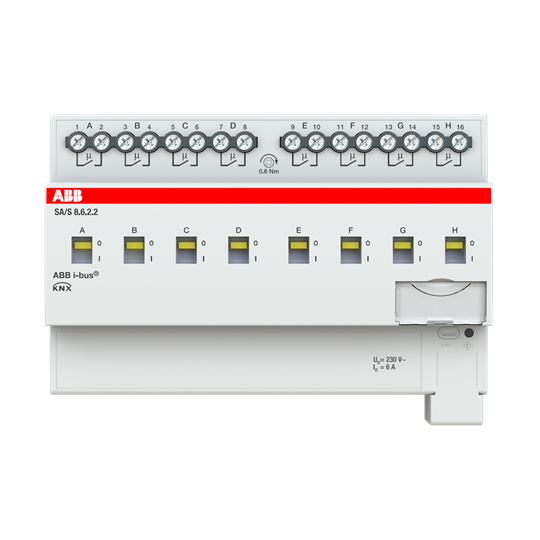
ABB SA/S8.6.2.2 Switch Actuator, 8-fold, 6 A, KNX
Original price was: ₹48,403.00.₹41,020.00Current price is: ₹41,020.00.
Description
The switch actuator uses potential free contacts to switch 8 independent electrical loads via the ABB i-bus® KNX. The device features a manual operation and displaying of the switching state of the outputs. The 6 A device is especially suited to switch resistive, inductive or capacitive loads. The device is powered by KNX and requires no additional power supply.
The device is a modular installation device (MDRC)
in proM design. It is designed for installation in
electrical distribution boards and small housings
with a 35 mm mounting rail (to EN 60715).
The device is KNX-certified and can be used as a
product in a KNX system → EU declaration of conformity.
The device is powered via the bus
(ABB i-bus® KNX) and requires no additional auxiliary voltage supply. The connection to the bus is
made via a bus connection terminal on the front of
the housing. The loads are connected to the outputs using screw terminals → terminal designation
on the housing.
The software application Engineering Tool Software (ETS) is used for physical address assignment and parameterization.
Device Dimensions 90 × 140 × 63.5 mm (H x W x D)
Mounting width in space units 8 modules, 17.5 mm each
Weight 0.41 kg
Mounting position Any
Mounting variant 35 mm mounting rail
Design ProM
Degree of protection IP 20
Protection class II
Overvoltage category III
Pollution degree 2
Materials Housing Polycarbonate, Makrolon FR6002, halogen free
Material note Fire classification Flammability V-0
Electronics Rated voltage, bus 30 V DC
Voltage range, bus 21 … 31 V DC
Current consumption, bus < 12 mA
Maximum current, device 8 × 6 A
Power loss, device ≤ 1.5 W
Power loss, bus ≤ 0.25 W
KNX safety extra low voltage SELV
Connections Connection type, KNX bus Plug-in terminal
Cable diameter, KNX bus 0.6 … 0.8 mm, solid
Connection type, load circuit Screw terminal with universal head (PZ 1)
Pitch 7.62 mm
Tightening torque, screw terminals 0.5 … 0.6 Nm
Conductor cross-section, flexible 1 × (0.2 … 4 mm²) / 2 × (0.2 … 2.5 mm²)
Conductor cross section, rigid 1 × (0.2 … 6 mm²) / 2 × (0.2 … 4 mm²)
Conductor cross section with wire end ferrule without
plastic sleeve
1 × (0.25 … 2.5 mm²)
Conductor cross section with wire end ferrule with
plastic sleeve
1 × (0.25 … 4 mm²)
Conductor cross section with TWIN wire end ferrule 1 × (0.5 … 2.5 mm²)
Length, wire end ferrule contact pin ≥ 10 mm
Certificates and declarations Declaration of conformity CE → 2CDK505253D2701
Ambient conditions Operation -5 … +45 °C
Transport -25 … +70 °C
Storage -25 … +55 °C
Humidity ≤ 95 %
Condensation allowed No
Atmospheric pressure ≥ 80 kPa (corresponds to air pressure at 2,000 m above
Pls click here for more information

Reviews
There are no reviews yet.